What's new

Have an old hydrospray system

Etowah

MEP001

Well-known member
Joined
Aug 30, 2007
Messages
16,667
Reaction score
3,937
Points
113
Location
Texas
So would I need relays for the high pressure functions since it requires a motor?
No, you need to connect those together on the outputs of the second stack at the rotary switch and run one wire straight to the contactor.
This is what I have for the tire cleaner, ps and fb since I’m using Flowjet what do I need to setup the hot, coin pulse wire, motor start and the timed hot wire?
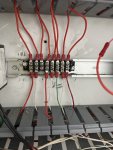
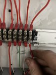
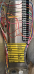
The only thing in that picture is a common hookup block. Each lead from the tire cleaner, presoak, and foam brush needs to connect straight from the rotary switch output to the solenoids for that bay. All the wires are color-coded, just remove the relays and directly couple the leads. Do you have a timer in the bay? The coin pulse wire doesn't need to come back into the room.
 

Kyle1

Member
Joined
Aug 19, 2022
Messages
102
Reaction score
4
Points
18
So basically connect the motor starter(orange), 24V hot(black), hp soap,wax,rinse, and spot free and the timed hot(red) all together inside the motor room. Then run one wire to the contactor. Which port should I connect it to?
 

MEP001

Well-known member
Joined
Aug 30, 2007
Messages
16,667
Reaction score
3,937
Points
113
Location
Texas
There's no reason for the timed hot to come back into the room. Timed hot needs to go straight to the rotary switch inputs, jumpered to inputs 11 and 21 (8 position) or 10 and 20 (10 position).

You don't connect anything "all together," each individual line from the switch needs to connect separately to each wire out to the solenoids. You're just going to remove the bank of green relays and connect the wire from the bay to the wire to the solenoids. The spot free is going to need something to isolate the bays, the rest do not.

A1 and A2 on the contactor are the power in for the contactor coil, but you need to run it through the thermal overload. It's most likely already wired where the power from the bay will go in at A1 and the common to the normally closed side of the thermal overload (marked as 96) with a jumper wire going from 95 to A2 on the contactor.

Here's my pictures again where you can see I removed the banks of relays and used terminal strips to make the connections:

Boxbefore.jpg

Boxafter.jpg
 

Kyle1

Member
Joined
Aug 19, 2022
Messages
102
Reaction score
4
Points
18
Ok so I’m here and the last connector is the motor starter wire and the first one is the 24v hot. I ran the hot to the transformer. Is that correct? And the motor starter wire I still don’t know where to run it I have fuses jumping to the top of the overload
 

Attachments

MEP001

Well-known member
Joined
Aug 30, 2007
Messages
16,667
Reaction score
3,937
Points
113
Location
Texas
image.jpg

I'm pretty sure that wire going into the top of the black block is the primary hot from the transformer. Trace it back to be sure. The remaining holder in the block is most likely a fuse holder. If this is correct, the five red wires with the black stripe are the "hot" wires that should go out to each bay. That's why there would be fuses on them. That wire doesn't connect to the motor starter. The wire that connects to A1 that you show in your picture above should come directly from the rotary switch from wires that are jumpered to the same positions as soap, rinse, and wax, but from the second stack. I can see in the photo that there are two wires connected to the A2 terminal on the contactor, which would be the "common" wires, which is correct. I was mistaken about the thermal overload, yours has separate thermal overloads above the contactor that break the power to the motors. The motor starter may run through that, I can't tell, but you should be able to trace it through if it does. It's possible the main "hot" to the bays goes through it, which would be best because if the thermal overload trips, it will also break the control voltage to the bay and keep a customer from losing money. I would rewire it that way if it's not already like that.
 

MEP001

Well-known member
Joined
Aug 30, 2007
Messages
16,667
Reaction score
3,937
Points
113
Location
Texas
I have a customer with a very similar setup with the contactors and thermal overloads. I'll go take some pictures of his and try to see how the overloads are wired. At least then I'll know if the overloads do break the control voltage when they trip. I know for sure they break the high voltage to the motor.
 

Kyle1

Member
Joined
Aug 19, 2022
Messages
102
Reaction score
4
Points
18
Yes that wire going into the fuse holder is going to the transformer
 

Kyle1

Member
Joined
Aug 19, 2022
Messages
102
Reaction score
4
Points
18
Which didn’t make much since because the second stack is typically the shorting stack for the motor controls
 

Kyle1

Member
Joined
Aug 19, 2022
Messages
102
Reaction score
4
Points
18
So I’m getting power to the bay however the timer is not coming on (I know it’s a good timer)
 

MEP001

Well-known member
Joined
Aug 30, 2007
Messages
16,667
Reaction score
3,937
Points
113
Location
Texas
The Electroswitch brand switches Kleen-Rite sells have the second layer make-before-break to keep the pump motor from briefly stopping when changing functions. The first layer is break-before-make so customers can't get two functions to come on at once. Coleman probably uses a different configuration.

Are you showing power between the leads label 24V HOT and 24V COMMON? Are you showing 24V AC?
 

Kyle1

Member
Joined
Aug 19, 2022
Messages
102
Reaction score
4
Points
18
Bottom 4 blocks are where it goes to the main circuit breaker
 

Attachments

MEP001

Well-known member
Joined
Aug 30, 2007
Messages
16,667
Reaction score
3,937
Points
113
Location
Texas
You should read 24V AC across them both. If you're checking to ground, they should each read 12V AC. The top two terminals with wires to them should read 208-240V AC across them.
 

Kyle1

Member
Joined
Aug 19, 2022
Messages
102
Reaction score
4
Points
18
It goes from the main panel to a circuit breaker to the TF
 

Attachments

Top