What's new

Wiring Slugbuster II PEM-55 to IDX AT411 - SS Vacuum

trs246810

Member
Joined
Sep 24, 2007
Messages
108
Reaction score
1
Points
18
I don’t think your fully understanding what you’re trying to do. You’re eliminating the 110 volts on the timer and switching it over to 24 volts. The 24 volt output from the timer is going to control the coil on the mercury replay. This will take the load off the timer.
Disconnect 110 volt wire on Terminal #1, pull that wire up to the top on the relay and put that wire into the seconded hole down on of the relay.
Put a jumper from Terminal #2 to terminal #5
The wire from terminal #6 disconnect this wire from the timer and pull this wire up to the top of the relay and connect it to the top terminal. Install a new wire from terminal #6 and route it up to the relay get connected to the bottom terminal on the mercury relay, this is the coil.
Run a wire from the transformer to the other side of the relay coil, the side of the transformer that has the white wire connected to it now.
Use crimp on spade terminal connectors. Like these http://www.homedepot.com/p/Gardner-...ated-Spade-Terminals-75-Pack-75-111/202522493 on your terminations, it makes for a better looking install.
you're right...I didn't get it. I know I'm probably trying your patience with my questions/just not getting it, but I really appreciate all of your help
 

2Biz

Thread Killer!
Joined
Nov 22, 2010
Messages
2,785
Reaction score
404
Points
83
Location
Ohio
Randy is exactly right...But let me take a stab at it. Start by Taking all the wires off the timer. Wire the transformer to 120v like the diagram on the transformer, white is 120v and black is common (I believe)…The screw terminals of the transformer attach to terminals 2 and 3 on the timer…It doesn’t matter which wire goes to which terminal as long as you end up making a complete circuit. Now put a jumper from terminal 2 to 5. This powers the “Line” side of the timer relay. Take a wire from terminal 3 “Common” to the bottom screw terminal of the mercury relay. Then take a wire from terminal 6 to the top screw terminal of the mercury relay. When the timer latches the relay, the circuit is complete and this will energize the coil on the mercury rely.

You’re not done. Now you need to take 120v and connect it to one of the lugs marked “line” on the top of the mercury relay. The other lug will be “Load” and will attach to the line side of the vac motors…The commons to the vac motors wire into the 120v common wire. Black wire is 120v line, white wire is 120v common….(Or Should be!) Basically like Randy and all have tried to tell you, the only load your timer will see now is the coil voltage on the mercury relay. The mercury relay handles all the vac motor load, isolating the vac motor load from the timer, thus protecting it from short circuits.

To power the Coin exceptor, the +/- wires of the exceptor wire them into termials 2 and 3 of the timer. The coin switch wires go to termianls 7 and 8 accordingly. Hope this helps…
 

MEP001

Well-known member
Joined
Aug 30, 2007
Messages
16,667
Reaction score
3,937
Points
113
Location
Texas
A few things wrong there:

Black is hot, white is common - that's standard electrical and should be adhered to for safety.

Load out (#6) from the timer goes to one of the screw terminals at the bottom when the relay is mounted upright, not the "top screw." 120V live goes to one of the lugs, the other goes to the motors.

He's using a Slugbuster, so only one coin switch wire (blue) goes to those terminals (#7). There will be an unused purple wire.
 

trs246810

Member
Joined
Sep 24, 2007
Messages
108
Reaction score
1
Points
18


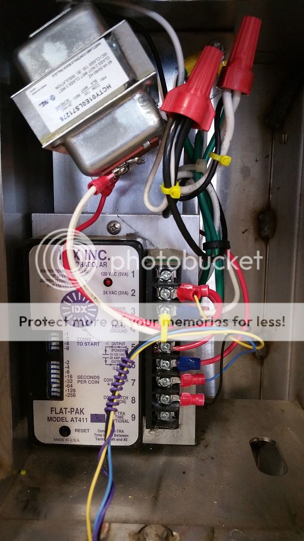
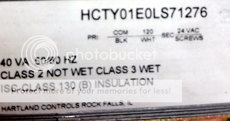
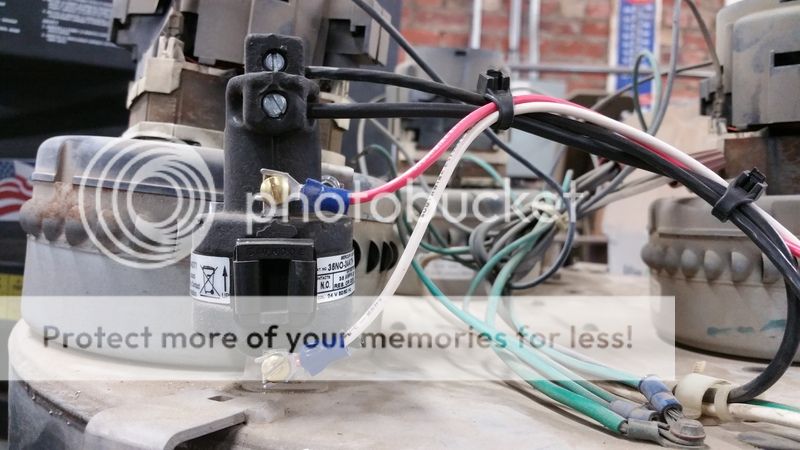
I finally got it going with help from you all. There is no longer any 110V on the timer. I think the transformer is one of those crazy deals where the black and whites are kind backwards...so, I went with that. I took a close up pic of that to show what it says on it. I'm obviously no electrician, but I tried to take all of the advice on here. I got some of the connectors to neaten things up. Thank you again to everyone.
 

2Biz

Thread Killer!
Joined
Nov 22, 2010
Messages
2,785
Reaction score
404
Points
83
Location
Ohio
I've wired many of that particular transformer where the white wire is attached to 120v just like the diagram shows. No issues yet! Also I didn't know the slugbuster only used 1 coin switch wire. My mistake! My coin exceptors use 2 wires. Glad you got it figured out! I haven't had the first issue with timers since adding the mercury relay. They are very robust.
 

MEP001

Well-known member
Joined
Aug 30, 2007
Messages
16,667
Reaction score
3,937
Points
113
Location
Texas
It's interesting that the coin acceptor works with its common connected to the coin switch common of the timer instead of combined with the common from the transformer. It must be jumpered internally which makes it really important to wire that timer correctly with 120V or you'd be electrifying the cherry switch with live voltage if you had the main leads backwards.
 

Randy

Well-known member
Joined
Sep 5, 2007
Messages
5,664
Reaction score
1,974
Points
113
trs246810, it looks good, you did a good job on the final installation. The Spade connectors make the install easier and it looks better. Now if you can do the other vac just like this one you should be Ok. Now you need to cut back on the amount of time you give your customers, I’d cut it back to 3 ½ minutes now and cut it again in about 6 months to 3 minutes.

The common from terminal #3 “Line common” to terminal #8 “coin Switch Common” are internally connected on AT411 timer.
 

trs246810

Member
Joined
Sep 24, 2007
Messages
108
Reaction score
1
Points
18
trs246810, it looks good, you did a good job on the final installation. The Spade connectors make the install easier and it looks better. Now if you can do the other vac just like this one you should be Ok. Now you need to cut back on the amount of time you give your customers, I’d cut it back to 3 ½ minutes now and cut it again in about 6 months to 3 minutes.

The common from terminal #3 “Line common” to terminal #8 “coin Switch Common” are internally connected on AT411 timer.
I agree on the time, and I like that idea on cutting back as well. I doubt I'll even wait that long, but we'll see. I have the other vacuum converted over now. They're still inside my shop, but I'm going swap them out with my old vacuums sometime this weekend. I got the old decals off and filters washed earlier. Graphics look great when new, but for me...it's not worth the hassle of replacing them. I'm okay with the plain stainless vs failing decals. I might be shooting myself in the foot by not maintaining some degree of flashy graphics?...I obviously have a lot to learn.
 

Randy

Well-known member
Joined
Sep 5, 2007
Messages
5,664
Reaction score
1,974
Points
113
I wouldn’t be too concerned about not having flashy graphics on your vacuums. I haven’t had flashy decals on my vacuums in over 16 years. I don’t think it’s hurt my vacuum business at all, my vacuums do very well. I’m at $1.25 for 3 ½ minutes and the guy down the road a mile is .75 for 5 minutes, he has flashy decals on his vacuums and I very seldom see anyone there vacuuming their car. Keep your vacuums cleaned out, well maintained and they’ll do well. I clean them out 3 times a week and beat down the filters once a week.
 

2Biz

Thread Killer!
Joined
Nov 22, 2010
Messages
2,785
Reaction score
404
Points
83
Location
Ohio
It's interesting that the coin acceptor works with its common connected to the coin switch common of the timer instead of combined with the common from the transformer. It must be jumpered internally which makes it really important to wire that timer correctly with 120V or you'd be electrifying the cherry switch with live voltage if you had the main leads backwards.
If he were wiring the timer using 120v, then your statement would be correct. But he wired it with 24v. The output terminals of the transformer are not marked + or -, so does it really matter in this case?
 

MEP001

Well-known member
Joined
Aug 30, 2007
Messages
16,667
Reaction score
3,937
Points
113
Location
Texas
It doesn't matter in this case, it was just a comment for future reference. It does explain why a guy with Adams vacs had customers getting shocked when they stood in water and dropped in quarters. The vacs were wired backwards and were not grounded.
 

2Biz

Thread Killer!
Joined
Nov 22, 2010
Messages
2,785
Reaction score
404
Points
83
Location
Ohio
Interesting.....So maybe there wasn't anything wrong with my instructions after all since "polarity" doesn't matter in a 24v system. And I really don't think there was anything wrong with referencing the bottom and top screws on the coil. Especially when I referenced the vac motor contacts as lugs on the top of the relay...so I'm having a difficult time figuring out what you thought was so wrong with my my post.
 

MEP001

Well-known member
Joined
Aug 30, 2007
Messages
16,667
Reaction score
3,937
Points
113
Location
Texas
I just wanted to be clear to him on the "top screw" part since when the relay is mounted the ones on top are the 120V in/out, and I saw where he could have put 24V in on one of those lugs and 120V live on the other from that instruction which would have smoked the transformer. I realize now you probably referenced his photo when you used "top screw."

I also felt it important that he had the black and white used correctly at least up to the relay and motors. I've seen people change motors without turning off power to the vac, and with polarity reversed at the motors they'd be live all the time.
 
Top