What's new

No power at meter box

Knight01

Member
Joined
May 8, 2021
Messages
75
Reaction score
20
Points
8
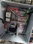
20220507_185149.jpg My 4 bay self serve has national pride equipment. One of the bays has lost power to the meter box. We have swapped the transformer from another bay that is working with the non-working transformer and it still gets no power to the meter box. But the transformer of the non-working bay works in the other. So, it doesn't appear to be a transformer. Issue.

The odd thing is we have 120v coming in on the two lines at the top but 0 volts coming out of the transformer. This is true of both transformers that were swappped/tested.

Has anyone run into this? Is there some reason power seems to be going into these transformers but not coming out?
 

Fatboy769

Living the American Dream
Joined
Sep 4, 2007
Messages
400
Reaction score
59
Points
28
I could be wrong, but it looks like the 2 wires feeding the transformer on the primary side are coming from L1 & L3 of the motor contactor, which would be 220V and not 120V. Can you take a pic of inside of the control box of a bay that is working?
 

Knight01

Member
Joined
May 8, 2021
Messages
75
Reaction score
20
Points
8
I could be wrong, but it looks like the 2 wires feeding the transformer on the primary side are coming from L1 & L3 of the motor contactor, which would be 220V and not 120V. Can you take a pic of inside of the control box of a bay that is working?
Yes, each wire is giving us 120v total of 240v. I'm not at the wash, but it is wired exactly the same as the working bays. We moved this one to a working bay and it worked fine, moved the working bay transformer to this bay and it didn't work. swapped them back to the way they were just to make sure the connections and ground was good. All wired the same to the transformer.
 

MEP001

Well-known member
Joined
Aug 30, 2007
Messages
16,667
Reaction score
3,933
Points
113
Location
Texas
What about the output of the transformer? You should read 24V AC across the screw terminals, or 12V AC from each terminal to ground.

You may have tripped the thermal overload on the contactor. The "best" way for those to be wired is the whole 24V circuit gets broken if it trips, which also disables the coin acceptor so people don't keep losing money. The thermal overload does not break the 3-phase power to the motor.
 

Fatboy769

Living the American Dream
Joined
Sep 4, 2007
Messages
400
Reaction score
59
Points
28
If that is the case, I would think it has to be something on the low voltage side. Have you unhooked the wires on the 24V side of the transformer and check to see if you get voltage coming out?
 

Knight01

Member
Joined
May 8, 2021
Messages
75
Reaction score
20
Points
8
If that is the case, I would think it has to be something on the low voltage side. Have you unhooked the wires on the 24V side of the transformer and check to see if you get voltage coming out?
Yes, there doesn't appear to be any voltage at the 'screws' that hold the wires. Unless there is somewhere else we need to touch to find the power. I bought a new transformer thinking that it had gone bad, but this one works in the other bays.

I wasn't sure if there could be something feeding back through the meter box or even in the switches that is preventing it from working.
 

Toms PTcarwash

Active member
Joined
Sep 13, 2021
Messages
267
Reaction score
128
Points
43
Location
Landisville, Pennsylvania
Yep, you need 208 or 240 when testing with your probes on the H3 and H4 of that transformer. Either one to ground is irrelevant as one leg will back feed through the transformer to ground.
I can't tell for sure from your pics, but it looks like the yellow wires from the motor contactor may go through fuse blocks before the transformer. If so that's most likely your problem a failed fuse. If not, check the three phase into your contactor. You should have 208 or 240 between all of the leads. l1 - l2, l2-l3 and l1 to l3. If not go back and check at your breaker the same way.
 

Dan kamsickas

GinSan Technician
Joined
Aug 31, 2007
Messages
588
Reaction score
677
Points
93
Location
Grand Rapids, MI
Like MEP said, is the power to the bay run through the overload? I'm not familiar with Schneider products(and too lazy to google) but the red button on yours appears to be the reset button and it sure looks tripped.
 

Toms PTcarwash

Active member
Joined
Sep 13, 2021
Messages
267
Reaction score
128
Points
43
Location
Landisville, Pennsylvania
The two yellow wires off the top of the motor starter look like they feed the transformer. They do not feed after the overload. It does look like they may go through a fuse block or some type of breaker just to the right of the motor starter. If indeed the overload is tripped, there probably is a leg coming into the panel without power.
 
Etowah

MEP001

Well-known member
Joined
Aug 30, 2007
Messages
16,667
Reaction score
3,933
Points
113
Location
Texas
Either one to ground is irrelevant as one leg will back feed through the transformer to ground.
This is incorrect. Each leg tested to ground is probably going to read 120V.
I can't tell for sure from your pics, but it looks like the yellow wires from the motor contactor may go through fuse blocks before the transformer. If so that's most likely your problem a failed fuse.
There would not be a fuse between the power pulled from the contactor and input to the transformer.
 

Dan kamsickas

GinSan Technician
Joined
Aug 31, 2007
Messages
588
Reaction score
677
Points
93
Location
Grand Rapids, MI
There would not be a fuse between the power pulled from the contactor and input to the transformer.
There doesn't need to be but many moons ago we did the same thing on our equipment. Had a 1 amp on the primary and a 4 amp on the secondary. Thought was that if the transformer failed it would trip the 1 amp and not let all the smoke out in the equipment room. It's pretty much overkill but it has been done. Much better to spend a bit more on a transformer with built in protection and not worry about it.

I wish this picture was clearer and wire chase covers were open to see where the wires are going better
 

Just Call Ben

New member
Joined
May 10, 2022
Messages
13
Reaction score
6
Points
3
So the picture is a little blurry but what I see (37 year veteran electrical contractor) is that the transformer is installed incorrectly. Please reply with a better pic of the wiring from transformer to contactor coil. Also provide a picture of the transformer label.

The ground (green wires) should not be connected to the transformer secondary. This creates a potential shock risk to anyone working around or operating the equipment. The ground should only be from case (control case, motor frame, etc.) to earth - real earth, copper water supply line, etc. THE ONLY PLACE GROUND SHOULD BE NEUTRAL BONDED IS AT THE MAIN ELECTRICAL SERVICE PANEL. Never ground any output of a transformer.
 

MEP001

Well-known member
Joined
Aug 30, 2007
Messages
16,667
Reaction score
3,933
Points
113
Location
Texas
Never ground any output of a transformer.
I didn't bother mentioning that because it has started an argument before, but you're right, especially if the transformer has two legs of 120V as a supply. I can't tell you how many times I've seen one output grounded, but it seems to work without a problem.
 

Dan kamsickas

GinSan Technician
Joined
Aug 31, 2007
Messages
588
Reaction score
677
Points
93
Location
Grand Rapids, MI
I didn't bother mentioning that because it has started an argument before, but you're right, especially if the transformer has two legs of 120V as a supply. I can't tell you how many times I've seen one output grounded, but it seems to work without a problem.
Where I've seen it cause weird problems is when someone loses a the connection to common on a coil and it develops a weird grounding loop and functions start turning on at random. Took me a bit to figure that one out. Damn loose screws.
 

MEP001

Well-known member
Joined
Aug 30, 2007
Messages
16,667
Reaction score
3,933
Points
113
Location
Texas
Where I've seen it cause weird problems is when someone loses a the connection to common on a coil and it develops a weird grounding loop and functions start turning on at random. Took me a bit to figure that one out. Damn loose screws.
Yup, I've been trying to stay away from combining all the common legs because of the issues it can cause. I had to rewire a whole equipment room once because someone swapped a transformer and in the process switched the line leads so everything was 48 volts on one side.
 

Roz

Well-known member
Joined
Oct 29, 2017
Messages
1,225
Reaction score
640
Points
113
View attachment 6022 My 4 bay self serve has national pride equipment. One of the bays has lost power to the meter box. We have swapped the transformer from another bay that is working with the non-working transformer and it still gets no power to the meter box. But the transformer of the non-working bay works in the other. So, it doesn't appear to be a transformer. Issue.

The odd thing is we have 120v coming in on the two lines at the top but 0 volts coming out of the transformer. This is true of both transformers that were swappped/tested.

Has anyone run into this? Is there some reason power seems to be going into these transformers but not coming out?
Timing is such that we have a similar situation.

Our box is a Kleen-Rite pump stand, started all of a sudden after working fine for 4-5 years. The small glass fuses used by our stepdown transformer are getting hard to find - had to go to three Home Depots to stock up on them. I can post a pic of our box on Monday.

Originally you can see something funky starting to happen we you turned to the LP Tire function. The Dixmor would start to flash the firmware version number, if you turned back to another function Dixmor would go back to normal counting. I have swapped out all the components in the pump stand box, and the Dixmor with good parts from other working boxes. Problem persists so I am guessing there is a mild short somewhere but really hard to find or isolate. Problem was fine when I disconnected the LP function in question then today the gremlin returned without warning. I need to see what function is triggering the blown fuse on Monday but this is getting unreal.
 

Don B.

Active member
Joined
Apr 7, 2022
Messages
122
Reaction score
59
Points
28
Timing is such that we have a similar situation.

Our box is a Kleen-Rite pump stand, started all of a sudden after working fine for 4-5 years. The small glass fuses used by our stepdown transformer are getting hard to find - had to go to three Home Depots to stock up on them. I can post a pic of our box on Monday.

Originally you can see something funky starting to happen we you turned to the LP Tire function. The Dixmor would start to flash the firmware version number, if you turned back to another function Dixmor would go back to normal counting. I have swapped out all the components in the pump stand box, and the Dixmor with good parts from other working boxes. Problem persists so I am guessing there is a mild short somewhere but really hard to find or isolate. Problem was fine when I disconnected the LP function in question then today the gremlin returned without warning. I need to see what function is triggering the blown fuse on Monday but this is getting unreal.
Just had the same problem a few weeks ago. Except mine was on the wax selection. Every time you turn the bay to wax the timer would flicker and do weird things. Then it started blowing the glass fuse. Turned out it was the wire from inside the panel in the equipment room that went to the wax solenoid on the pump. Over the years it had rubbed from vibration and wore the insulation off the wire. Bare wire was grounding itself against the pump stand frame and blowing the fuse. Sounds like you have a direct short.
 
Top