What's new

Need help.

Joined
Aug 18, 2019
Messages
85
Reaction score
10
Points
8
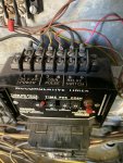
Ok long story short is I ordered new doors for each one of my bays. The doors are equipped with dixmor led 7, Cryptopay, 10 position switch, and a sensortron acceptor. I think the biggest problem I’m having is I’m using the dixmor in the bay and also have a idx timer in the pump room. Do I need to get rid of the idx and run straight off of the dixmor? Because my idx does not illuminate and kick off when time reaches 0. It seems I also have a couple extra wires on my strip. I know one is coin pulse and not sure what the other one is just yet.
 

Attachments

Joined
Aug 18, 2019
Messages
85
Reaction score
10
Points
8
I think if someone had a wiring diagram of the control box in the pump room I could probably make something work.
 

MEP001

Well-known member
Joined
Aug 30, 2007
Messages
16,667
Reaction score
3,937
Points
113
Location
Texas
You only have eight positions now, right? Assuming in clockwise order with Stop at the top, tire cleaner, presoak, soap, foam brush, rinse wax, spot free, there are currently no unused wires. You'll remove coin pulse to the timer in the room and timed load back to the switch, so you'll have two unused wires. Just take the timer out and make note of the color wires that go to the coin signal and timed load terminals so you can mark as unused. The rest you can figure out in the bay easily. With your current setup, the screw terminals at the top of the switch are timed load (labeled as 11 and 21) and will be ignored. That corresponds to STOP on the dial Go counter-clockwise from there on the back, 12 will be the next screw terminal and will correspond to the first function clockwise from STOP, etc. Those are from the first layer, the second layer appears to be only for the motor starter. That will give you the colors of the functions to hook up to the new door.
 
Joined
Aug 18, 2019
Messages
85
Reaction score
10
Points
8
You only have eight positions now, right? Assuming in clockwise order with Stop at the top, tire cleaner, presoak, soap, foam brush, rinse wax, spot free, there are currently no unused wires. You'll remove coin pulse to the timer in the room and timed load back to the switch, so you'll have two unused wires. Just take the timer out and make note of the color wires that go to the coin signal and timed load terminals so you can mark as unused. The rest you can figure out in the bay easily. With your current setup, the screw terminals at the top of the switch are timed load (labeled as 11 and 21) and will be ignored. That corresponds to STOP on the dial Go counter-clockwise from there on the back, 12 will be the next screw terminal and will correspond to the first function clockwise from STOP, etc. Those are from the first layer, the second layer appears to be only for the motor starter. That will give you the colors of the functions to hook up to the new door.
this is what I have inside my PR.
 

Attachments

Joined
Aug 18, 2019
Messages
85
Reaction score
10
Points
8
On my bar inside of the box I have a spot that goes out for timed it’s the double yellow on bottom. When bay is in function it has 24v when it has timed out it drops to 14v is that normal?
 

Attachments

Randy

Well-known member
Joined
Sep 5, 2007
Messages
5,672
Reaction score
1,983
Points
113
The firsr thing you need to completely eliminate the timer in the equipment room and then get out the volt meter and start tracing wires to see which one goes where or does what. I love it when nothing is labeled.
 
Joined
Aug 18, 2019
Messages
85
Reaction score
10
Points
8
The firsr thing you need to completely eliminate the timer in the equipment room and then get out the volt meter and start tracing wires to see which one goes where or does what. I love it when nothing is labeled.
I’ve pulled out the timer. I wired my hot and common straight into the bus bar. I have a pink and yellow wire left over we will cal that the timed back to the box and the coin pulse wires. I have every low pressure function working as designed. My issue I’m having is that when I wire up my motor latch the high pressure function turns on and will not turn off even after time has expired. I’m wondering if I have a wiring issue with the door causing it not to turn off. I might just try another door in that place to see if it acts any different.
 

Attachments

Joined
Aug 18, 2019
Messages
85
Reaction score
10
Points
8
Just so I’m clear. I figure the motor latch will be the brown wire that is going to the backside of the relays tied into all the black wires that goes to each relay. The timed from the box would be the black wire coming into the front of the relay. Is that right?
 

Attachments

MEP001

Well-known member
Joined
Aug 30, 2007
Messages
16,667
Reaction score
3,937
Points
113
Location
Texas
Just remove all the relays and bases and run the motor out from the switch direct to the contactor. The latching relays were there for the start/stop buttons in the bays and won't work anymore.
 
Joined
Aug 18, 2019
Messages
85
Reaction score
10
Points
8
Just remove all the relays and bases and run the motor out from the switch direct to the contactor. The latching relays were there for the start/stop buttons in the bays and won't work anymore.
I’m working on that now.
 
Joined
Aug 18, 2019
Messages
85
Reaction score
10
Points
8
So the key was removing the timer and the relays. I also don’t have anything wired up to the timed hot and all functions operate as they are supposed to. Now I can work on cleaning up the boxes inside of the pump room. Thanks for everyone’s help today. I couldn’t have figured it out without y’all.
 

MEP001

Well-known member
Joined
Aug 30, 2007
Messages
16,667
Reaction score
3,937
Points
113
Location
Texas
The timed hot goes directly from the timer to the rotary switch. It's something you eliminated in the wiring when you removed the old timer.

Now you have two spare wires for adding a function or two.
 
Joined
Aug 18, 2019
Messages
85
Reaction score
10
Points
8
The timed hot goes directly from the timer to the rotary switch. It's something you eliminated in the wiring when you removed the old timer.

Now you have two spare wires for adding a function or two.
Yes sir that sure will make it easy when adding something cool in the future!
 

Randy

Well-known member
Joined
Sep 5, 2007
Messages
5,672
Reaction score
1,983
Points
113
Marshall it wouldn’t hurt to install an inline fuse on the 24 volt power supply to protect the circuit if you don’t already have one installed.
 

Randy

Well-known member
Joined
Sep 5, 2007
Messages
5,672
Reaction score
1,983
Points
113
I have a 5 amp fuse inline
That's good. You'd be surprised at how many car washes I've worked on that don't have any kind of protection. A while back I had a car wash owner send me a new Dixmor LED-7 that he wanted replaced under warranty that had burned up and melted. He had removed the fuse because it kept blowing, he thought the timer should be on warranty.
 
Joined
Aug 18, 2019
Messages
85
Reaction score
10
Points
8
That's good. You'd be surprised at how many car washes I've worked on that don't have any kind of protection. A while back I had a car wash owner send me a new Dixmor LED-7 that he wanted replaced under warranty that had burned up and melted. He had removed the fuse because it kept blowing, he thought the timer should be on warranty.
No sir I was a airplane mechanic in the air force and also worked as a service manager at a car dealership. I’m aware of the protection of fuses and circuit breakers. I appreciate your concern though. You never know out there anymore.
 
Top