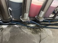
The pumps have 3 outlets, one separate incoming line to each membrane. The only thing chained together is the permeate and reject outlets from the top of the pump. Will attach a picture. Thanks for your time and patience.
Car Wash Forum
You are using an out of date browser. It may not display this or other websites correctly.
You should upgrade or use an alternative browser.
You should upgrade or use an alternative browser.
Fine tuning RO System
- Thread starter robfaf
- Start date

Buckeye Hydro
Well-known member
So they ARE plumbed in parallel. Strange. I'd replumb to put them in series. You will dramatically reduce the concentrate flow to drain. Put your concentrate needle valve and flow gauge downstream of the third membrane.
Buckeye Hydro
Well-known member
I also notice you have copper/brass fittings on the permeate... this is to be avoided. The permeate will corrode those fittings from the inside out.
I thought it was strange too. This is not my first RO system but it’s a lot more complex than my others. I have two pumps feeding the 3 membranes, is it possible that I continue to use that setup but plumb in series instead? Would I need to change anything on the outlet side of the membranes to accomplish that?
Buckeye Hydro
Well-known member
Two pumps? I'd check the model number of the pumps and look into their specs.

Buckeye Hydro
Well-known member
If you plumb them in series, AND if they are 2500 gpd 4040 membranes, then:
Permeate = ~7500 gpd = 313 GPH
Concentrate = 3 gpm = 180 GPH
Feedwater - you need a pump that will put out 493+ gallons per hour at whatever pressure you need for your membranes.
Permeate = ~7500 gpd = 313 GPH
Concentrate = 3 gpm = 180 GPH
Feedwater - you need a pump that will put out 493+ gallons per hour at whatever pressure you need for your membranes.
They’re both 10gpm Sat-Rite pumps. Plenty of pump. I just don’t understand why the Coleman system is built this way. The guage for pressure isn’t coming off of the pump outlet; it’s after the membranes. So I could have pressure but I don’t know what it is. In any case it’s still not filtering properly.
Buckeye Hydro
Well-known member
Have you considered getting a new RO?
Buckeye Hydro
Well-known member
10 gpm = 600 gph. Like you said - they will move plenty of water.
You need a liquid filled pressure gauge after the pump(s). See here: https://www.buckeyehydro.com/pressure-gauges-1/
What a strange RO!
You need a liquid filled pressure gauge after the pump(s). See here: https://www.buckeyehydro.com/pressure-gauges-1/
What a strange RO!
It is strange. I’d like a new one eventually, but I wanted to see what I could do to make it work more efficiently for the time being since it’s built into the entire self serve skid. It’s producing water around 10ppm, but it fluctuates. Since I replaced all of the membranes I was hoping to make it better!
Buckeye Hydro
Well-known member
Maybe call the company and see if you can get a manual.
At 10ppm, personally I'd call it good. What membranes did you install?
Russ this is a Coleman system built on the pumping unit skid. It was put there for install efficiency but is a huge pain to work on because it was an afterthought and everything is tucked under a tank and hard to access. It works fine but you will cuss it when you occasionally have to work on it. Is there logic behind pushing the membranes to a higher pressure to reduce TDS? Does this also affect longevity of the membrane?
The gauge is measuring the pressure "vessel" created by pump pressure and the space outside of the membranes.
Last edited:
Buckeye Hydro
Well-known member
All the settings/variables are in play here. Concentrate flow... can't be adjusted. that will affect pump output pressure relative to the spec pressure on the membrane. If you feed membranes low pressure you may get inadequate or excessive concentrate flow... reducing the system efficiency. I which I could put my hands on that system to get it tuned up... if that is even possible.
The plumbing is generally confusing, the manuals from Coleman don’t help. I’ve tried every possibility with this one. Here’s where I am:
My permeate is at 10ppm. Rejecting 6gpm, producing 3gpm, "pump pressure” is around 50psi.
New membranes. Verified feed flow. Incoming water is around 40-50PSI Flush valve replaced to new, not sticking open. But it’s a normally closed valve, yet the reject flows through it? I’m still confused about that part. The plumbing there is membrane > reject outlet > into regulator > into flush valve > out to reject tank (which is high on the wall, and I added a check valve to the line to prevent backfeeding)
I added a check valve to the main delivery line as well as replaced all spot free check valves on the entire system to prevent backflow. My tank TDS has stabilized since then, getting close to being at 10ppm.
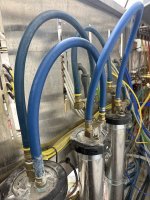
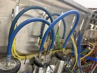
The guage showing 50PSI is not connected to the pump output. It’s coming off of a tee on the reject regulator. I’ll attach a pic -black arrow is reject line coming in to the regulator and going into the flush valve, blue circle is the 1/4 in line coming off of the regulator into the guage, red circle is the guage. Blue hose on the top right is the permeate coming into the flow guage and out into the tank. I don’t think this plumbing makes sense, or should the pressure be 150psi AFTER the membranes?
Cars aren’t being spotted, I’m happy that the tank is stabilizing under 30PPM, but I’d like to see that pressure corrected, unless a solution is a guage on the actual pump output before the membranes. Everyone I’ve discussed with is saying that guage specifically should show 150-180 psi.
Thanks everyone for your help, I’ll figure this out eventually!
My permeate is at 10ppm. Rejecting 6gpm, producing 3gpm, "pump pressure” is around 50psi.
New membranes. Verified feed flow. Incoming water is around 40-50PSI Flush valve replaced to new, not sticking open. But it’s a normally closed valve, yet the reject flows through it? I’m still confused about that part. The plumbing there is membrane > reject outlet > into regulator > into flush valve > out to reject tank (which is high on the wall, and I added a check valve to the line to prevent backfeeding)
I added a check valve to the main delivery line as well as replaced all spot free check valves on the entire system to prevent backflow. My tank TDS has stabilized since then, getting close to being at 10ppm.
The guage showing 50PSI is not connected to the pump output. It’s coming off of a tee on the reject regulator. I’ll attach a pic -black arrow is reject line coming in to the regulator and going into the flush valve, blue circle is the 1/4 in line coming off of the regulator into the guage, red circle is the guage. Blue hose on the top right is the permeate coming into the flow guage and out into the tank. I don’t think this plumbing makes sense, or should the pressure be 150psi AFTER the membranes?
Cars aren’t being spotted, I’m happy that the tank is stabilizing under 30PPM, but I’d like to see that pressure corrected, unless a solution is a guage on the actual pump output before the membranes. Everyone I’ve discussed with is saying that guage specifically should show 150-180 psi.
Thanks everyone for your help, I’ll figure this out eventually!
Buckeye Hydro
Well-known member
It's customary to have a pressure gauge:
- Before and after the sediment filter (aka prefilter). This tells you what your plumbing line pressure is, and what the "filter out" pressure is. You can monitor the delta between the two as an indicator of when the sediment filter needs to be changed. If the "filter out" pressure drops below a certain pressure, most RO's have a low pressure switch that will shut the system off to protect the pump.
- After the pump. This shows you the pressure being delivered to the membranes. The membranes are the component in the system that is sensitive to water temperature and water pressure. Use membranes spec'ed at a pressure your pump is capable of delivering.
Last edited:
Why do you keep replying if you have nothing productive to add to the converstaion?Rub Goldberg