What's new
Car Wash Forum

This is a sample guest message. Register a free account today to become a member! Once signed in, you'll be able to participate on this site by adding your own topics and posts, as well as connect with other members through your own private inbox!

Adding a Carbon Filter

Probably worth a replumb to 1 membrane or 2 depending on your holding tank size. Will save on everything basically
And makes my recommendation more viable.
With the right fittings you could even hook it up with a pair of washing machine hoses.
Get a few Melt-Blown filter cartridges for the Big Blue housing, too. They're frequently overlooked!
 
Probably worth a replumb to 1 membrane or 2 depending on your holding tank size. Will save on everything basically
So, if mine is running in series, I would just replumb to end after 2 membranes?
I am out of town until Tuesday, I will send more pictures on Wednesday.
Thanks again.
 
Yours is yet another RO system in the car wash sector with an atypical configuration. Rather than flow gauges for Concentrate and Permeate, your system has gauges for feedwater and permeate. More often than not when we see these oddly configured systems it's at a carwash.

Hopefully you have a needle valve that allows you to control your concentrate flow... and you will just have to do a little arithmetic as
feedwater - permeate = concentrate
 
So, if mine is running in series, I would just replumb to end after 2 membranes?
I am out of town until Tuesday, I will send more pictures on Wednesday.
Thanks again.
If you replumb it so you effectively only have two membranes plumbed in series, you'd then have a 4000 gpd nameplate capacity RO system. Expected flows would be:
permeate = 4000/1440 = ~2.8 GPM
concentrate = minimum of 3 GPM
Feedwater = 3+2.8 = 5.8 GPM

The guidance printed to the left of your flow gauges indicates with only two membranes you need feedwater to be at least 3 times the permeate flow. This would make sense only if the pump outlet feeds two membranes plumbed in parallel rather than in series. Given that, I'll bet your current config has the pump feeding two membranes and each of those membranes feeds a second membrane plumbed in series.

If you're going to replumb the system, make sure:
1. You have a valve on the system that will allow you to throttle the pump output, and
2. If you effectively cut permeate flow and feedwater in half - those flows will still register/be visible on your flow gauges.
 
Last edited:
If you replumb it so you effectively only have two membranes plumbed in series, you'd then have a 4000 gpd nameplate capacity RO system. Expected flows would be:
permeate = 4000/1440 = ~2.8 GPM
concentrate = minimum of 3 GPM
Feedwater = 3+2.8 = 5.8 GPM

The guidance printed to the left of your flow gauges indicates with only two membranes you need feedwater to be at least 3 times the permeate flow. This would make sense only if the pump outlet feeds two membranes plumbed in parallel rather than in series. Given that, I'll bet your current config has the pump feeding two membranes and each of those membranes feeds a second membrane plumbed in series.

If you're going to replumb the system, make sure:
1. You have a valve on the system that will allow you to throttle the pump output, and
2. If you effectively cut permeate flow and feedwater in half - those flows will still register/be visible on your flow gauges.
I have a needle valve controlling the concentrate that goes to the drain. I do not have a valve after the pump before the membranes.
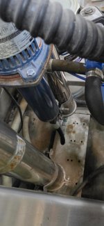
It looks to be plumbed in series, with the pump only feeding one membrane, I attached another picture showing that.

The feedwater runs into the prefilter, to the "Inlet water flow gauge", to the pump which feeds the bottom of the back right stainless steel membrane housing (as you are looking at the system from the front), to the top of the front right PVC membrane housing, to the bottom of the front left PVC housing, from there, the top blue hose on the front left PVC housing runs to the "Permeate flow gauge", then to the spot free storage tank. But from the front left PVC membrane housing, it also runs to the top of the back left stainless steel membrane housing, and at the bottom of that one is the concentrate valve that runs to the drain.
Hopefully that makes sense.
As you look at the pictures, you can see each membrane has a hose running to the membrane next to it going clockwise.
If I replumb to remove two membranes, how would each membrane housing be connected? Just once following the flow of the water through the membranes(either at the top of bottom of each housing)? Or would there be a hose on top even if the flow suggested to connect at the bottom of the housings?
Thanks for all your help.

 

Attachments

  • Screenshot_20260329_003426_Messages.jpg
    Screenshot_20260329_003426_Messages.jpg
    236.8 KB · Views: 10
It’s a bit difficult to trace how everything is connected from the photos.
  • It’s unclear where the line goes after the blue Big Blue filter.
  • The blue hose on top of the membrane appears to be disconnected and not connected to anything.
It seems like there might be some missing components.

I’ve only worked with HANNA RO systems, so I can only speak from that experience, but…
I posted a response to Buckeye Hydro that answers your concerns. Any other thoughts you have are appreciated. I can attach more pictures also. Thanks.
 
You have a (vertical) multistage centrifugal pump, so it is ok the throttle the output. If you go from 4 to 2 membranes you'll need to throttle the pump output. Typically, this is done with a globe valve. You'd buy and install that.
You'd replumb your membranes. Some things you'll need to understand.
  • Membrane housings typically have 4 ports. You'll use three of the four and plug one on the four.
  • Permeate comes out of the center tube of the membrane and the center port of the housing.
  • Concentrate comes out of the body of the membrane at the end opposite of the input.
  • Membranes have brine seals and the direction the membrane is installed in a housing is critical.
  • Concentrate from Membrane 1 feeds Membrane 2
  • Permeate outlets from the housings are connected and then run to the permeate flow gauge.
  • You'll want to know and monitor the TDS in the feedwater and (at a minimum) the TDS in the combined permeate flow.
  • A more typical configuration than you currently have would include a permeate flow gauge and a concentrate flow gauge (rather than a feedwater flow gauge). The concentrate flow gauge would have a built in needle valve, or it would read the flow after a needle valve.
Are you sure you are up to rebuilding your RO system? There's a fair bit to understand and you'll not have luck finding someone to walk you through it (remotely or onsite) free of charge.

Russ
 
I am definitely not sure if I am up to rebuilding the RO system. I just did not know what it took exactly. I can follow everything you wrote, so I appreciate that.
I might be better off adding the carbon filter for now. But if I did rebuild, I would need a smaller carbon filter. Thank you.
 
I posted a response to Buckeye Hydro that answers your concerns. Any other thoughts you have are appreciated. I can attach more pictures also. Thanks.
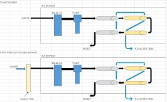
I tried to illustrate it to make it easier to understand.
Is this what you are trying to achieve?


@Buckeye Hydro
Is my understanding of the connections correct?
The black arrows indicate the feed water flow, and the blue arrows indicate the RO water.
 

Attachments

  • RO System Diagram.jpg
    RO System Diagram.jpg
    89.2 KB · Views: 8
I tried to illustrate it to make it easier to understand.
Is this what you are trying to achieve?


@Buckeye Hydro
Is my understanding of the connections correct?
The black arrows indicate the feed water flow, and the blue arrows indicate the RO water.
Thanks, yes, that is what I am trying to achieve. But others have suggested, accurately, that i do not need 4 membranes, but going to 2 would be fine. So I was thinking of replumbing the RO to have only 2 membranes, but was not sure how difficult it is.
 
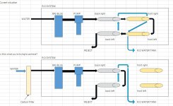
I had some time, so I sketched this out while keeping the stainless membrane housings.
(I also matched the hose colors for clarity.)

I’ll leave the carbon tank side to those with more expertise.
Is this roughly what you had in mind?
 

Attachments

  • RO System Diagram2.jpg
    RO System Diagram2.jpg
    93.2 KB · Views: 9
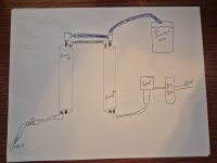
Sorry for the crude drawing, but is this how the plumbing would look if I went down to 2 membranes? Then the carbon filter would come in before the big blue filter?
Thanks again for everyone's help.
 

Attachments

  • 17750690853716999771681484748501.jpg
    17750690853716999771681484748501.jpg
    1.7 MB · Views: 14
Back
Top