MEP001
Well-known member
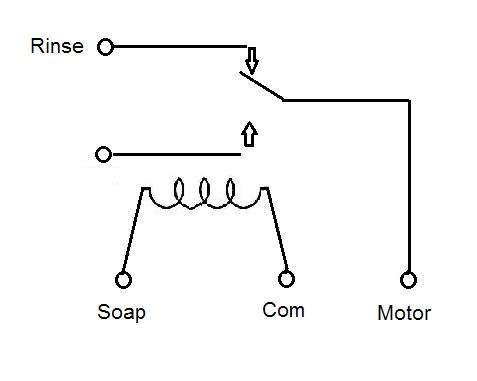
It's not to take the load off anything, it was a suggestion in case he used a N.O. solenoid because he didn't have an extra wire from the bay for the rinse solenoid. He never replied to that question so I still don't know if that's the case or not.2Biz said:Why do you need to power the solenoid with a SPDT relay to take the load off the timer? Surely the water solenoid doesn't draw that much? Maybe 6 watts or so? What am I missing here?


")