What's new

Programmable Relay or PLC

2Biz

Thread Killer!
Joined
Nov 22, 2010
Messages
2,785
Reaction score
404
Points
83
Location
Ohio
Would there be interest to share PLC or Programmable Relay programs and Knowledge here on the forum? I don’t want to step on any toes... That’s why I would like opinions as to whether this would be Politically Correct on the forum or not. I have an Idec Controller coming that I am going to use for an Air Blowdown system for my Tri-Foam. It can easily be expanded to include my FB or whatever? It only took me a few hours working with the software to understand it and make a program that will work. Wasn't as complicated as I thought it would be.

It would be nice to have a place to share knowledge and compare ideas. Your thoughts?
 

MEP001

Well-known member
Joined
Aug 30, 2007
Messages
16,667
Reaction score
3,937
Points
113
Location
Texas
Siemens actually has a forum that has helped me with a couple problems. There are users there that put what I've learned about programmable relays to shame.
 

2Biz

Thread Killer!
Joined
Nov 22, 2010
Messages
2,785
Reaction score
404
Points
83
Location
Ohio
It can be very complex. I work in manufacturing and all of the new CNC machines use PLC's and ladder logic for control. The guys on those forums are at that level! Not our level! From what I've learned in just a few hours, our programs are relatively simple...I was able to come up with something that works in a very short time.

I'll give this thread a few days to get some opinions as to whether it's ok to proceed. Then I'll start off by posting what I came up with.

Basically it's a 4 output relay. Input (1) is for a thermostat. Input 2, 3, and 4 is bay inputs. (I have three bays with Tri-Foam). There is a 2 second delay for each bay to keep the program from running in case someone is spinning through the selector switch. It has two blow down relay/timers per bay. One to blow down shortly after use, and the second to blow down say maybe 10 minutes after use when the foam has had time to solidify. If the tri-foam is used again within this time frame, the system resets and starts over. Once it runs through the program, it resets and awaits another use. What triggers the system is when the tri-foam is in use for more than 2 seconds and shuts off. Then the relays are triggered to run the program. This same program could be modified easily to control other systems like an air/washer fluid blowdown. Like a Polar Freeze Guard system at a fraction of the cost....So far I have about $400 in the controller, usb programming cable, software, and solenoid mainifold....Then I'm adding some LEDs in the enclosure to see the status of the unit at a glance and some switches to manually run each solenoid if I need to. Fun Stuff!
 

pitzerwm

Active member
Joined
Aug 28, 2007
Messages
3,693
Reaction score
10
Points
36
Location
Tri-Cities, WA
2Biz, This is a good idea, I have a couple in the Library, under presentations, but I can create something that will help everyone. there are lots of uses and fun with these units.
 

Randy

Well-known member
Joined
Sep 5, 2007
Messages
5,662
Reaction score
1,971
Points
113
2Biz, Please do share the information you have learned.
 

mac

Well-known member
Joined
Sep 3, 2007
Messages
3,558
Reaction score
790
Points
113
It's quite common for advances in a field to come from people working in other fields. That's been the case for centuries. When you consider that much of the technology in our so called industry is 50 years old, we welcome any input from more cutting edge industries. This will also keep the manufacturers on thier toes, and give the visitors here much needed input.
 

2Biz

Thread Killer!
Joined
Nov 22, 2010
Messages
2,785
Reaction score
404
Points
83
Location
Ohio
Time to pay it forward! If anybody gets rich off this, please don't forget where you got it! :)

Here is the program. You'll need to open it in the Idec Software to run it.

http://bcoweb.com/photos/blowdown.lsc

You can find the software, free trial version here:

http://us.idec.com/Product/Software/WindLGC.aspx

It is a trial version that lets you create and run your program. You just won't be able to upload it to your PLC unless you buy the full version.


Here is the ladder program as displayed after its designed using the software. Its in the simulation mode.


MEP001

Well-known member
Joined
Aug 30, 2007
Messages
16,667
Reaction score
3,937
Points
113
Location
Texas
This is the program for the units I put in each bay - it delays the high-pressure pump and the RO, purges the bay hose with air after each use and closes the "STOP" button circuit on the D.A.N. when no function is selected.


I've made a dozen other programs including a tri-foam controller that overlaps each color to make six, and a RO production system controller that I made sure doesn't have the biggest problems of most of the systems I've seen.
 

2Biz

Thread Killer!
Joined
Nov 22, 2010
Messages
2,785
Reaction score
404
Points
83
Location
Ohio
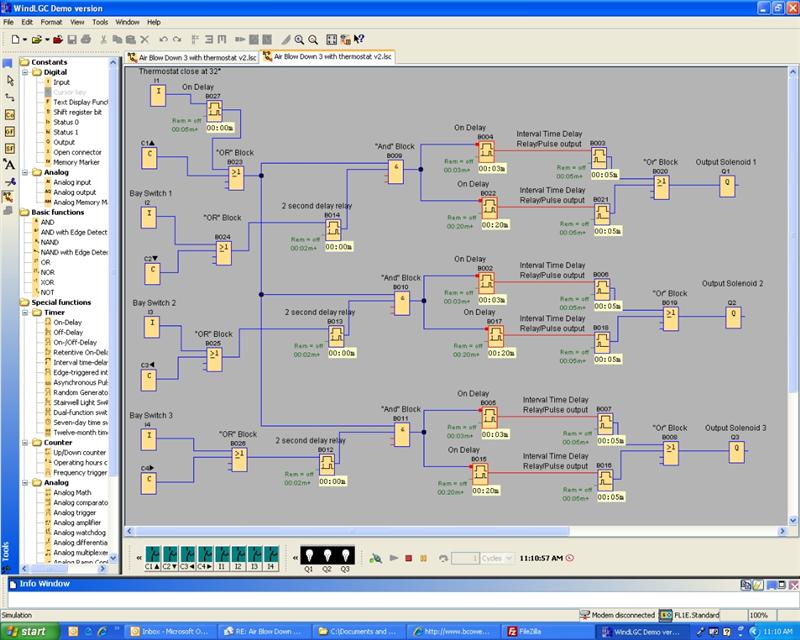
I will explain how this works....On the left you have (4) inputs, I1, I2, I3, and I4. I1 will be hooked to a thermostat set to make at 32° or whatever temp you have the thermostat set at. They are connected to an "AND" block, meaning that all inputs to this block have to be on before the relay makes.

I2, I3, and I4 (Bay 2, 3, and 4) are all inputs from the bays that have the Tri-Foam. They are hooked to a 2 second ON delay relay set for 2 seconds. I explained how that works in my previous post. When the relay makes, the next block is the "AND" block. Since the connection has been made from both the bay and thermostat, it allows flow through it to the next stop. Which is a double set of On Delay Relays and Interval Time Delay Relays w/ pulse output. The timers on these relays are such that the top row delays for a preset amount of time then turns the output (Solenoid) on for a preset amount of time. The second row is basically the same, only the On delay is set to like 5 or 10 minutes for the second blowdown. The "OR" block is just a simple connection block because you can't have two relays going to a single output. The "OR" block allows throughput from either circuit.

Now to explain how the simulator works. At the bottom of the diagram, you see (4) green buttons. I1, I2, I3, and I4. They are your inputs. The 3 lightbulbs beside the switches are your outputs/solenoids. In order for the circuits to work, you have to turn on I1 or the thermostat. Then if you turn on either of the other three switches (Bay inputs) nothing happens. The program only starts when power is turned off to any of the switches, which is what we want. Then the relays all work together to give you the output you are looking for. Its easy to change the time values of each relay...

So...It took me about 3-4 hours playing with the program to see how it worked...Once I got started it only to me about an hour to get to the finished product.

The ONLY ISSUE I see with my program, is that when the simulator starts, it cycles each relay (turning on the output) just one time then it sets waiting on bay activity. I'm wondering if all controllers do this. It may not do it on the controller. I don't have it yet to test. On order! But I'm relieved I have a usable program for when it does come in.

Any suggestion on how to make it better, I'm all ears!
 

2Biz

Thread Killer!
Joined
Nov 22, 2010
Messages
2,785
Reaction score
404
Points
83
Location
Ohio
Looks like the Logosoft and Idec software are identical! Somebody is sleeping together! :) :) :)
 

MEP001

Well-known member
Joined
Aug 30, 2007
Messages
16,667
Reaction score
3,937
Points
113
Location
Texas
It looks identical to the Siemens Logo that I use, probably even takes the same cable to program.
 

JIMT

Member
Joined
Sep 4, 2007
Messages
143
Reaction score
0
Points
16
Location
Toledo, Oh.
Add CURSER KEYS and OR blocks to your INPUTS.

You can then test the entire system operation by pressing the appropriate “arrow key” on the LOGO/SmartRelay.

BTW…IDEC SmartRelay is the private label version of Siemens LOGO with a 6 month delay for new products.
Source - http://www.sea.siemens.com/us/SiteC...roducts/2008-04-15_2/CompetitiveBriefLOGO.pdf
I was told by IDEC that they make this PLC under contract for Siemens and they are allowed to sell it also.

I use the IDEC Microsmart CPU for a coin vacuum system and IDEC FA2Js for Broadway in bay automatics. It took me a lot more than I few hours to be able to program the automatics. My suggestion is to set a one bay system but not in the bay to test the program and to look for problems. I have found that unexpected things happen.
Once you have it working your will want to control all sorts of systems. It is additive.
JIMT
 

2Biz

Thread Killer!
Joined
Nov 22, 2010
Messages
2,785
Reaction score
404
Points
83
Location
Ohio
Add CURSER KEYS and OR blocks to your INPUTS.
I'm uncertain what the cursor keys do? The OR blocks were pretty easy to figure out where to use. Can you elaborate?

I'm sure an automatic would take more than a few hours to program. The blowdown is pretty basic, but challenging all the same. Especially since I've never programmed one before. I don't have an auto, but see how this can be addictive. I bought a 12" x 12" enclosure to house the relay and am already wondering if there is enough room for an Expansion Module!
 

cantbreak80

Maybe I need new clubs
Joined
Feb 10, 2008
Messages
1,125
Reaction score
573
Points
113
Location
CO
For your system to operate, your thermostat must provide the input voltage. You can use a jumper wire to activate a test run or you can add an external switch to your panel to override the stat input…(24v hot) but that adds cost and installation time.

By using Cursor Key inputs, you can eliminate the external bits and use the relay’s 4 arrow buttons for your test buttons…actually, ESC+UP Arrow for example.

Delete I1 to B009 connection
Insert C1 (Cursor Key) below I1
Insert OR
Connect I1 to OR input
Connect C1 to OR input
Connect OR output to B009

Program C1 to function as a switch…Double click C1 block on your grid…select Simulation Tab…Select Switch
Now, when you want to test or give the system an early blow down, Depress ESC + UP Button and I1 is energized.
Add C2 thru C4 to your other inputs and you can now cycle each bay…all without external switches, jumper wires or running out to the bay.


I usually install a 5 minute Delay On after a thermostat input…just in case the temperature “hovers” around the setpoint…i.e. thermostat input must be on for 5 minutes before activating the program. Especially if you’re using a thermister thermo-control like a Dixmor Weepmiser.
 

2Biz

Thread Killer!
Joined
Nov 22, 2010
Messages
2,785
Reaction score
404
Points
83
Location
Ohio
Thanks for the detailed explanation! I understand now....I'll post a new diagram after I've made the changes. You saved me a lot of wiring and the external switches....Thanks!
 

2Biz

Thread Killer!
Joined
Nov 22, 2010
Messages
2,785
Reaction score
404
Points
83
Location
Ohio
Ok...I think I got it! This is some pretty neat stuff.

I think I've asked this before, but maybe you can help once again. In Simulation mode or at the startup of simulation mode, all the relays cycle through once activating the outputs. Then resets...Does the controller do the same thing on startup?

BTW...I have all the time values set low for testing. Once I get my controller, I'll reset all the time values for what I want and then upload the program to the controller.


cantbreak80

Maybe I need new clubs
Joined
Feb 10, 2008
Messages
1,125
Reaction score
573
Points
113
Location
CO
I think I've asked this before, but maybe you can help once again. In Simulation mode or at the startup of simulation mode, all the relays cycle through once activating the outputs. Then resets...Does the controller do the same thing on startup?
It's because you have inputs inverted on your On Delays B004, B022, B002, B017, B005, and B015. That's why their state is ON in your image. Do you really want to do that?

To change it, double click on the relay's input trigger...the black box will disappear and a message box will display "Trg not inverted".

BTW...To make your program easier to modify/edit without a computer you make want to make some changes to your block numbering:
Start at the Q for each line and work backwards...adding blocks until you get to I.
Repeat for each line until you have a complete program...the blocks will be numbered sequentially.
 

2Biz

Thread Killer!
Joined
Nov 22, 2010
Messages
2,785
Reaction score
404
Points
83
Location
Ohio
I need for the program to run only after the bay is switched on (No Output) then switched off (I have output after specified time delays). The only way I can get my program to run when the Input is switched to off, is to Invert the input to the On Delays at B004, B022, B002, B017, B005, and B015. If the triggers are not inverted, when the Input is switched on, the program runs through its cycle. I don't want the blowdown to run while the tri-foam is in use. Surely I'm missing something?

Thanks for taking the time to help with this! Please bare with me. I've only looked into using these relays and the software a very short time. I'm surprised at how quickly this is all making sense though.
 
Top